I remember when I learned for the 1st
time about Conway's Game Of Life – a Cellular Automata model in a
Polish equivalent of Popular Mechanics for youth: “Mlody Technik”
(Young Technician) in 1984. I have been at the time a technical high school
freshman. I
immediately recognized how great a simulation platform a computer would
be for this model. Unfortunately I did not have a computer or even an
access to one. I spent long hours simulating colonies on a piece of a
graph paper.
In the early 2000-s when I was learning
C#/.NET I did a C# implementation as an exercise. The GUI is a bit awkward, but simulation is fairly
fast and can emulate quite big arrays of the cells. My son loves to
play with this program even though I never had time to refine it or get rid of few bugs. It has edit/load/save abilities, user
can set, unset cells with a mouse click, zoom in and out and enable
grid lines. My 9-year old has no problem with that, so I guess everybody could get used to it.
 |
Modern GUI C#
implementation of Game of Life.
|
 |
C# Game of Life -
program setup.
|
 |
C# Game of Life - with
elevated zoom and grid lines enabled for easy editing.
|
In the meantime I made numerous console
based ports in C language for DOS and Linux. It is always fun. Now, while this is quite easy with modern computers and programming languages, it is not the same on some old slow CPU and limited memory platform using low level machine language or slow interpreted language like BASIC for example.
Recently I realized that I have never
did a C-64 port. Being a Commodore aficionado, I found this a great
oversight, so I got to work.
My first tries using BASIC and Power-C
for C-64 and C-128 were disappointing. My algorithm was very slow. I
realize that with some clever coding I could do a fast simulation in
higher level language. Perhaps one day I will try to
invent some clever GOL simulation algorithm in C which will be fast enough for practical application. Even though I like to work directly on a retro hardware, (emulator does not emulate look and feel), this time I wanted to try the cross-platform IDE called C64 Studio (I love the demo helicopter game that comes with it). I
installed it, made sure it points to my installation of Vice emulator
and got to work. I researched some GOL implementations for CBM
platform on the internet and have been impressed by this great piece
of 6502/C64 code by 'Ruk':
Although Ruk's goal was minimum size
and maximum speed, so the program is not really packed with features, it is
still very impressive what you can do with this ancient by today's standard hardware. He
does some pretty clever encoding of the colony so the calculating of
the next generation is real fast and code is extremely compact. It
fits in less than 256 bytes with full screen emulation/presentation
and sound.
I did not match Ruk's implementation of
GOL speed and tiny size, however these were not my goals (well, maybe the speed was, but I lack the skill at the moment). Instead my program is
packed with practical features and makes up for slower speed and
(much) bigger code size with numerous functions like: built-in demo colonies,
random colony generator, colony full screen screen editor and disk I/O. Although
program takes 16 blocks on a disk, the colony files are only one
block in size (binary encoded, 40*25/8 = 125 bytes is all it takes to encode 1000-cell colony) and save and load pretty fast. The
simulation speed is also satisfactory with about 2 ¼ generations per
second.
Conway's Game Of Life – the rules.
The world of Game of Life (GOL)
consists of a 2-dimensional array of cells, which can have a dot
(live cell) or be empty. The next generation of dots is calculated by
counting the live neighbors on adjacent cells. E.g: please refer to
illustration below, where the central cell is live (has a dot) and
has 8 adjacent cells, which contain a total of 3 live neighbors.
 |
A cell with adjacent
cells.
|
The rules of death and life are as
follows:
- Death -
Each dot that has 1 or no live
neighbors dies out of loneliness.
Each dot that has 4 or more live
neighbors, dies out of the overcrowding.
- Life -
On each empty cell that has
exactly 3 live neighbors, a new dot is born.
Each dot that has 2 or 3 live
neighbors, remains in its live status.
Computer algorithm.
On today's fast hardware, the directly
implemented algorithm causes no speed concerns. The cells can be
encoded in bit fields or directly in a BOOLEAN or character array.
The cells of the arrays are iterated sequentially and the neighbors
number is calculated for each cell separately and the next generation
of the colony can be generated to the separate memory buffer and then
presented in whatever form to the user.
However working with the 1 MHz 8-bit
CPU with limited RAM is different. There are memory and performance
considerations. We want to avoid too much of the data copying
operations (internal colony representation vs. screen presentation,
copying data between buffers etc.) and really huge arrays. In my
implementation I decided to compute the next generation directly in
the text screen memory (the world is a 1000 cells array, 25 rows 40
columns each). To avoid artifacts on the screen while the next
generation is calculated, double buffering technique could be used.
However I chose a technique to encode the screen codes for dying and
born cells of the next generation to be as closely represented on the
screen to the live and empty cells of a current generation as
possible. For example the dot (live cell) is presented with screen
code $51, which is a big filled oval dot. The dying cell is
represented with code $57, which is a very similar semi-graphical
character to the one represented by code $51, except it just has a
small not filled with color hole inside (donut like) while remaining
the same size. Therefore when the next generation calculating
algorithm is marking the cells for dying, their screen presentation
do not change significantly. Just a little hole appears briefly in
the middle of each dying cell, which has a nice side effect for the
presentation function anyway. Even better screen code match was found
for a new-born cell. Note that it is not desired to have new born
dots appear on the screen before the whole array is calculated. The
screen code $60 is represented on the screen as empty space, just as
the empty cell is represented by code $20, also resulting with an
empty space on the screen. For the computer algorithm these are 2
different codes (desirable feature). However for the user, there is
no change on the screen when the algorithm marks cells where a new
dot is born in the next generation. Thanks to that I avoided
necessity of performing double buffering and switching screen memory
banks. After next generation is calculated, quick routine converts
the died and new born screen codes to the empty and dot codes (fully
filled) and the next generation is again calculated in the endless
loop. The end-user presentation in effect is quite pleasant and
appears as a seamless generation after generation display.
Apparently the assembly routine
calculating the next generation of the colony was the most
challenging for me. The performance of the simulation depends on it
the most. I used direct GOL rules implementation with few tricks and
optimization techniques. The resulting binary image is under 4 kB in
size. Considering the amount of features packed, I consider this a
moderate achievement. Thanks to the speed of the machine language, I
achieved satisfactory performance without affecting the readability
of the code or necessity to use advanced colony encoding techniques.
Although it is my desire in the future to do just that and make the
code blazing fast, for now I will settle for 2 generations per second
speed as I need some more 6502 assembly language practice to achieve
better results in code.
Zero page indexing addressing mode and
various counters are used by the algorithm to cycle through screen
memory cells from left upper corner to right-lower corner of the
screen (YIND – column counter is used to iterate through cells in a
row and then ZPG vector is increased by 40 and YIND zeroed at the
beginning of each next row).
Here is the routine which is the heart of the GOL simulation algorithm:
; calculate the next generation
; Theory of operation:
; The screen memory is scanned from start to end.
; Each row is iterated with pointer ZPGA1 and index Y.
; Addressing mode (ZPGA1),Y is used. Register Y is
; reloaded with column counter yind, which is incremented
; accordingly at the end of the loop,
; then ZPGA1 is increased by 40 at the start of the next row.
; The number of neighbors is calculated for each cell.
; Depending on the # of neighbors, the cell is encoded
; to either die (DCELL), be born (BCELL) or remain unchanged.
; After this procedure, the 'disp' routine should be called
; to convert died cells to empty spaces and born cells (BCELL)
; to live cells (LCELL).
next
ldx #0
stx xind ; initialize row index
stx yind ; initialize column index
stx nbct ; initialize neighbor cells counter
lda #<MSCR ; initialize ZPG address buffer
sta ZPGA1 ; and current cell address counter
sta smct
lda #>MSCR
sta ZPGA1+1
sta smct+1
nl0 ; left neighbor check
ldy yind
beq nl1 ; skip left neighbor check if column=0
dey ; decrement ZPGA1 pointer (left side neighbor)
lda (ZPGA1),y ; load cell's value
cmp #LCELL ; if not a live cell
beq nl000
cmp #DCELL ; or not a 'died' cell (in this iteration)
bne nl00 ; jump to nl00
nl000
inc nbct ; increment neighbors count
nl00
ldy yind
nl1 ; right neighbor check
cpy #MAXCOL ; if cell at the far right side
beq nl2 ; then skip right neighbor check
iny ; increment ZPGA1 pointer (right side neighbor)
lda (ZPGA1),y ; load cell's value
cmp #LCELL ; if not a live cell
beq nl111
cmp #DCELL ; or not a 'died' cell (in this iteration)
bne nl2 ; jump to nl2
nl111
inc nbct ; increment neighbors count
nl2 ; north neighbors check
lda xind
beq nl4 ; skip north neighbors check if row=0
jsr sb40zpga1 ; subtract 40 from ZPGA1 (north neighbor)
ldy yind
lda (ZPGA1),y ; load cell's value
cmp #LCELL ; if not a live cell
beq nl222
cmp #DCELL ; or not a 'died' cell (in this iteration)
bne nl22 ; jump to nl22
nl222
inc nbct ; increment neighbors count
nl22 ; north-west (NW) neighbor check
ldy yind
beq nl3 ; skip NW neighbor check if column=0
dey ; decrement ZPGA1 pointer (NW side neighbor)
lda (ZPGA1),y ; load cell's value
cmp #LCELL ; if not a live cell
beq nl2220
cmp #DCELL ; or not a 'died' cell (in this iteration)
bne nl220 ; jump to nl220
nl2220
inc nbct ; increment neighbors count
nl220
iny ; return ZPGA1 pointer to north neighbor's cell
nl3
cpy #MAXCOL ; if cell at the far right side
beq nl33 ; then skip the right neighbor check
iny ; increment ZPGA1 (right side neighbor)
lda (ZPGA1),y ; load cell's value
cmp #LCELL ; if not a live cell
beq nl333
cmp #DCELL ; or not a 'died' cell (in this iteration)
bne nl33 ; jump to nl33
nl333
inc nbct ; increment neighbors count
nl33
jsr rldsm2zpga1 ; reload smct to ZPGA1
nl4 ; south neighbor check
lda xind
cmp #MAXROW ; if row at maximum,
beq nl6 ; skip south neighbors check
jsr add40zpga1 ; add 40 to ZPGA1 (now ZPGA1+Y -> south neighbor's cell)
ldy yind
lda (ZPGA1),y ; load cell's value
cmp #LCELL ; if not a live cell
beq nl444
cmp #DCELL ; or not a 'died' cell (in this iteration)
bne nl44 ; jump to nl44
nl444
inc nbct ; increment neighbors count
nl44 ; south-west (SW) neighbor check
ldy yind
beq nl5 ; skip SW neighbor check if column=0
dey ; decrement ZPGA1 (SW side neighbor)
lda (ZPGA1),y ; load cell's value
cmp #LCELL ; if not a live cell
beq nl4440
cmp #DCELL ; or not a 'died' cell (in this iteration)
bne nl440 ; jump to nl440
nl4440
inc nbct ; increment neighbors count
nl440
iny ; return ZPGA1 pointer to south neighbor's cell
nl5
cpy #MAXCOL ; if cell at the far right side
beq nl6 ; then skip the right neighbor check
iny ; increment ZPGA1 (SE side neighbor)
lda (ZPGA1),y ; load cell's value
cmp #LCELL ; if not a live cell
beq nl55
cmp #DCELL ; or not a 'died' cell (in this iteration)
bne nl6 ; jump to nl6
nl55
inc nbct ; increment neighbors count
nl6
jsr rldsm2zpga1 ; reload smct to ZPGA1 (restore address of the row)
lda yind ; store old column# before incrementing
sta yold ; for further calculations
inc yind ; increment column#
lda yind
cmp #(MAXCOL+1)
bne nl66
lda #0
sta yind
jsr add40smct ; increment smct (point to the next row of cells)
inc xind ; increment row#
nl66 ; now mark the cells to live/die/be born
ldy yold
lda (ZPGA1),y ; load current cell
cmp #LCELL ; check if a live one
beq nl666
cmp #DCELL
bne nl7 ; not a live one, jump to nl7
nl666 ; live cell, determine its fate
lda nbct ; load neighbors counter
cmp #0 ; if nbct<2, cell dies
beq nldie
cmp #1
beq nldie
cmp #2
beq nlnext
cmp #3 ; if nbct==3, cell does not change
beq nlnext ; if nbct>3, cell dies
nldie
lda #DCELL
ldy yold
sta (ZPGA1),y ; update cell with 'died' code
clc
bcc nlnext ; prepare for next cell
nl7 ; not a live cell, determine its fate
lda nbct ; load neighbors counter
cmp #3 ; only if nbct==3, a new one is born
bne nlnext
lda #BCELL
ldy yold
sta (ZPGA1),y ; update cell with 'born' status.
nlnext
lda xind ; check if the end
cmp #(MAXROW+1)
beq nlend ; yes, jump to nlend
jsr rldsm2zpga1 ; reload smct to ZPGA1
lda #0 ; initialize neighbors counter
sta nbct
jmp nl0 ; do the next cell
nlend
rts
Before saving, colony's editor screen is encoded into binary form (so each byte holds information about 8 cells) into buffer with this routine:
; convert screen (editor's format) into binary format
; store in colb buffer
encodeed2colb
lda #<MSCR
sta ZPGA1
lda #>MSCR
sta ZPGA1+1
lda #0
sta gpct ; gpct - encoded byte
sta gpct+1 ; index to colb buffer (encoded colony)
lda #8
sta gpbyt ; gpbyt - bit counter
ee2cloop000
ldy #0
lda (ZPGA1),y ; load byte from screen memory
cmp #'*' ; is it live cell?
bne ee2cloop002 ; no, branch to ee2cloop002
lda gpct ; load encoded byte to Acc
ldx gpbyt ; load bit counter to X
ora encodearr,x ; set the bit in Acc masked by encodearr,X
sta gpct ; store updated encoded byte
ee2cloop002
dec gpbyt ; decrement bit counter
lda gpbyt
beq ee2cloop001 ; if byte counter is 0, branch to ee2cloop001
ee2cloop000a
jsr SystemZone.inczpga1 ; increment ZPG1 (screen memory)
lda ZPGA1 ; check if end of screen memory
cmp #<MESCR
bne ee2cloop000
lda ZPGA1+1
cmp #>MESCR
beq ee2cfinished
clc
bcc ee2cloop000 ; do next bit
ee2cloop001 ; single byte encoding finished
ldx gpct+1 ; load encoded colony buffer index
lda gpct ; load encoded byte
sta colb,x ; store byte in the encoded colony buffer
inc gpct+1 ; increment index to encoded colony buffer
lda #8 ; reload bit counter
sta gpbyt
lda #0 ; reset encoded byte
sta gpct
clc
bcc ee2cloop000a ; do the next bit
ee2cfinished
rts
Here is how the encoded binary format colony look like, this example is a built in demo colony:
; shooter colony, binary encoded
dcshootenc
!byte 100 ; first byte is the number of encoded bytes that follow
; encoded colony
!text B00000000,B00000000,B00000000,B00000000,B00000000
!text B00000000,B00000000,B00000000,B00000000,B00000000
!text B00000000,B00000000,B00000000,B00000000,B00000000
!text B00000000,B00000000,B00000000,B00000000,B00000000
!text B00000000,B00000000,B00000000,B00000000,B00000000
!text B00000000,B00000000,B00000000,B11000000,B00011000
!text B00000000,B00000000,B00000001,B01000000,B00011000
!text B01100000,B00110000,B00000001,B10000000,B00000000
!text B01100000,B01010000,B00000000,B00000000,B00000000
!text B00000000,B01100000,B01100000,B00000000,B00000000
!text B00000000,B00000000,B01010000,B00000000,B00000000
!text B00000000,B00000000,B01000000,B00000000,B00000000
!text B00000000,B00000000,B00000000,B00000000,B00001100
!text B00000000,B00000000,B00000000,B00000000,B00001010
!text B00000000,B00000000,B00000000,B00000000,B00001000
!text B00000000,B00000000,B00000000,B00000000,B00000000
!text B00000000,B00000000,B00000000,B00000000,B00000000
!text B00000000,B00000000,B00000000,B01110000,B00000000
!text B00000000,B00000000,B00000000,B01000000,B00000000
!text B00000000,B00000000,B00000000,B00100000,B00000000
Features and presentation.
After the welcome screen, user presses
a key and the help screen is displayed showing keyboard shortcuts to
the functions of the program. Due to the presentation environment
being text based, that information is not present on the screen
during colony editing or simulation, therefore it is a good idea to
read and memorize this screen or print it before proceeding.
 |
Game of Life simulator
- help screen.
|
In the next step, user is presented
with the program's start menu. Possible choices consist of two
template/demo colonies, ability to start with an empty editor or
editor filled with random colony. There is also a load from file
option available and option to terminate the application
(confirmation is required).
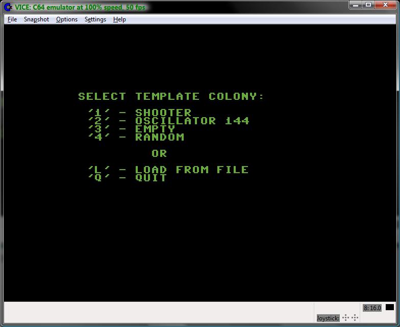 |
Game of Life - start
menu.
|
Depending on the user's choice, the
editor starts filled with the colony or empty. Editor encodes the
empty and life cells differently than the simulator. The empty cells
are represented by minus '-' signs, while the life cells are
represented with asterisks '*'. This approach has 2 advantages:
User can recognize immediately in
what mode the application is currently working (remember – there
is no extra text information, the whole screen is taken by colony
data presentation).
The empty cells done with minus
sign present a grid which makes it easier for user to design/modify
the colony.
 |
Game of Life - editor
screen filled with random colony.
|
In editor, user can position the cursor
(visible as a reverse color rectangle) using cursor keys on the
keyboard and alter the cell status with space key. Other possible
functions are 'H' to display help screen, 'C' to clear all the cells
(requires confirmation), 'R' to fill cells with random values
(requires confirmation) and 'Q' to exit the editor and start
simulation. At the exit, user is prompted to save the colony to file,
which can be skipped.
 |
Game of Life - exit
editor, save to file prompt.
|
If user chooses to save the colony to
file, a prompt appears to enter the colony file name.
 |
Game of Life - save
colony, file name prompt.
|
The simple file name editor allows to
enter alpha-numeric string of up to 12 characters in length. User can
press DEL key to remove incorrectly entered characters. If the
entered file name is empty (RETURN key pressed with the cursor
positioned at the 1st character of the file name), the
Save operation is considered as canceled and program proceeds to
simulation. Otherwise, the program attempts to save the colony to
file. In case of I/O error, there is no action. Extension “.COL”
is added to the file name automatically.
Simulator starts in paused mode. User
can immediately see that program entered simulation mode because the
cells are now presented differently on the screen (Illustration
below).
 |
Game of Life – paused
simulator.
|
Pressing any key starts the simulation.
Please note the donut style cells (see Illustration below), which are
the cells marked to die in the next generation by the algorithm.
Newborn dots are not visible until the next generation is fully
created and the screen codes converted to the full dots or spaces
accordingly.
(NOTE: on the screen shot below, not
all the cells that are supposed to die in the next generation are yet
marked like donut, because the screen shot captured the screen in the
middle of the process)
 |
Game of Life - running
simulation.
|
At any moment during simulation user
can choose to quit application (requires confirmation), pause it, go
to editor and alter/save the colony, display the help screen or go
back to start menu (requires confirmation) using the keyboard
shortcuts presented on the help screen at the program start up.
 |
Game of Life - quitting
the application.
|
 |
Game of Life - the fun
is over.
|
Thank you for visiting.
Marek Karcz
9/15/2013.


