You will not believe (or perhaps most of you seasoned Commodore equipment users will) how much time in troubleshooting costed me putting an old diskette from e-bay in my Commodore disk drives.
It all started when my GEOS-128 set arrived from e-bay. Two manuals, 6 diskettes, all visually in a very good shape. The smell of these items suggested they possibly spent long time at the bottom of some closet. No indication of dampness. The pages in one of the books were only yellowed a little bit. The diskettes looked clean (perhaps except one, which only you could notice by looking at the surface at certain angle that there is some residue on it, which of course I noticed after all my troubles).
So, I opened the GEOS manual on the page with instruction how to boot the system for the first time, I put the system diskette in my primary drive (I use three 1571 drives, first one with Jiffy DOS installed and a uIEC-SD device, this setup works very nice with CP/M) and booted it. The 1st disturbing thing to notice was a whining sound from the drive. The disk did not boot of course. I made a few extra attempts with the same result.
"OK" - I thought. - "This is just an old disk, I will try to read its directory."
This of course did not work, but perhaps because it is a GEOS diskette?
Anyway, I tried in my other drives. Then I put some of the other diskettes that arrived with the set in all of my drives and tried to read them. None has worked.
This is kind of expected and it happens with old diskettes. The most disturbing part however was that my normally working disks now has stopped reading too in any of my disk drives.
"What is it?" - I thought. - "The day of broken Commodore drives?".
I realized it is rather unlikely that all of the disk drives went down the same day. But, still clueless, I opened my first drive to see for obvious mechanical issues. Did not find any (even magnetic head looked clean). Next I opened my worst 1571 (the one I owned the longest time and looks like the one most worn down by time) and attempted to align it. Nothing worked. I gave up some time in the morning.
The next day I got my revelation moment - "A dirty head!".
Yep! That was it. These old disks must have been stored in some not too good conditions, perhaps for some time exposed to moisture and/or high temperature. Their magnetic layer literally peeled off their surface and it deposited on magnetic heads choking them up! I swabbed them with alcohol and they are all like new again.
I know most of the Commodore or any retro computer equipment users know this stuff. But if you are a young inexperienced retro computer technology enthusiast, beware! Better to have a designated disk drive (instead of your best primary disk drive) for reading/examining the diskettes from unknown sources, especially if they are listed as untested or their condition is not mentioned by the selling party. And if your equipment stops working as expected, first look for the obvious reasons (like neglected maintenance in my case, head cleaning was long overdue, regardless of the dirty diskettes put in recently). I swabbed the heads but I think it is better (and more convenient) to use one of those head cleaning diskettes, which unfortunately are not being made these days. I saw them on e-bay though and I am going to order some for myself.
Cheers!
Saturday, March 22, 2014

Sunday, November 17, 2013
Serial port communication on Apple IIc.
Apple
II was a very good and quite popular 8-bit machine in its time. It
features a hardware UART for RS-232 port communication that can still
be used today. Even from the BASIC language level, it is quite simple
to make the use of that feature. I happen to own Apple IIc, which I did not own in the 80-s. I bought the set of the computer, monitor, printer and software on e-bay out of curiosity. I have to admit I also like the look of the little machine which was advertised as a portable Apple II. It would no pass the standards of portability today, however in the early to mid 1980-s it was enough if the computer had a carrying handle and/or some sort of a case. Apple IIc has an UART/RS-232 built in permanently as it does not feature the expansion bus as its bigger brother Apple II does.
The
basics are as follows:
On
the PC side setup port to 300 baud (default apple 2c speed), 8 bit,
no parity, 1 stop bit, no flow control. Your terminal may or may not
offer customization of the parameters listed below. I used the Hyper
Terminal Private Edition. Other emulators may offer the customization
of the listed below properties in the different form. Follow you
terminal emulator's documentation:
Terminal
setup: ANSI
ASCII
setup: append line feed to incoming line ends, force incoming data to
7-bit ASCII.
Apple IIc side - issue command PR#2.
Now
all the output goes via serial wire to a PC.
Alternative
baud setup:
Apple
2c:
After
PR#2 command, press CTRL-A and then the baud code:
CODE BAUD
1B 50
2B 75
3B 110
4B 135
5B 150
6B 300
7B 600
8B 1200
9B 1800
10B 2400
11B 3600
12B 4800
13B 7200
14B 9600
15B 19200
16B 115k
To
setup the serial port speed from basic, use print chr$(1) followed by
the speed code, e.g:
10
pr# 2
15
print chr$(1);"15b"
20
print "hello world!"
30
goto 20
Above
program will redirect output to serial port and setup transmission
speed to 19200 baud.
PC
side - follow manual of your terminal emulator software to match the
baud rate of the Apple 2c.
The
automatic line trace in BASIC is automatically on (seems to be a
feature) when the output is redirected to a serial line. Perhaps
because such mode of working was intended for development/debugging
purpose. Anyway, it is good to include NOTRACE just after PR#2 in
your program to turn this feature off. There are several other (than
baud rate) parameters that can be setup for serial port after IN#2 or
PR#2. Just use PRINT CHR$(1);"{command_code}" to set them
up.
Here
are the command codes:
Data
format
Code Data
Length Stop bits
0D 8 1
1D 7 1
2D 6 1
3D 5 1
4D 8 2
5D 7 2
6D 6 2
7D 5 2
ASCII
setup:
Code Effect
I echo
output to the screen
K do
not send line feed after carriage return
L send
line feed after carriage return
Parity:
Code Parity
Check Mode
0P none
1P odd
2P none
3P even
4P none
5P MARK(1)
6P none
7P SPACE(0)
Example
BASIC program setting up 9600 baud, 8-N-1, send LF after CR:
20
PR#2
30
NOTRACE
40
PRINT CHR$(1);"14b"
50
PRINT CHR$(1);"0d"
60
PRINT CHR$(1);"0p"
70
PRINT CHR$(1);"l":rem it is small "L".
For
some reason, I have to setup 7 bit data length, 1 stop bit on the PC
side, even though Apple works in 8-1 mode. I will have to look into
this later, for now I don't understand why the discrepancy.
On
Linux (R-Pi) I used 'putty' or just plain "cat /dev/ttyUSB0"
to receive data from apple.
To
redirect input and output to serial port, so you can work on apple
from remote terminal, type on apple:
IN#2
{CTRL-A)14b
PR#2
From
this moment, whatever you type in the terminal emulator on the PC
workstation is really happening on Apple. The PC workstation acts a a dumb terminal
for the Apple computer. Pretty cool. You can actually create a boot
diskette for the Apple to load up and execute all necessary serial
port initialization commands at the boot time and with a PC/laptop
connected to the Apple via serial port (or USB with USB to serial converter) you do not need a display monitor with the Apple computer.
This way of working with Apple II of course may have some
limitations, which I am sure user would discover very quickly.
However it is possible to work with BASIC and text based programs in
this manner.
Happy
retro-computing!
Thank
you for reading.
Marek
Karcz, 11/17/2013
Saturday, November 16, 2013
Apple IIc as a dumb text terminal.
Using
you old computer hardware with modern equipment.
If you
happen to have Apple II (IIc) computer and you think it is just
taking space, do not put it in the trash, sell or donate just yet.
The thing is, you own it because perhaps you purchased it long time
ago, or got it as a gift and at some time liked it. It gave you hours
of fun and helped to introduce you into the computing world. Whatever
the reason, it may make your heart heavy to let it go. Well, you can
still use it! Consider this - Apple IIc has a good serial port
hardware driver and can be easily interfaced with modern equipment
that is also equipped with a serial or USB ports (with USB to serial
converter). All that is needed on the Apple side is a terminal
emulation software and a serial null-modem cable adaptor that
converts the Apple's mini-din to the DB-9 connector seen on modern PC
computers. All the information I needed in order to turn my Apple IIc
into the serial dumb terminal I found here:
and
here:
First
I prepared 3 blank floppy disks for Modem MGR software. I used
AppleWorks software which I happen to have purchased with my Apple
IIc. To transfer the Modem MGR images to Apple, you need ADT Pro
client on the Apple side and a server on the PC side. Both are
available on the internet as well as detailed instructions how to
install and configure them, so I will not duplicate it here. Just
check out the web site:
After
the transfer of Modem MGR software, I had 3 disks: Installation,
Utilities and Work. First I inserted and booted the Installation disk
on my Apple and follow the instructions. I configured the software to
work in 80-column mode (menu option 2) video driver, non-smart modem
(menu option 10) and saved the configuration back to the work disk.
Next I
connected the Apple's serial port to my DSL (Damn Small Linux)
server. The server runs a script:
#!/bin/bash
while
true
do
/sbin/getty
-L 9600 ttyS1 vt100
done
The
connection via standard serial cable and the mini-din to DB-9 adapter requires no null-modem connector, since the mini-din to DB-9 adapter cable is already a NULL modem. However I used the null modem serial
cable and wondered for some time why this did not work. Then I had to
add extra null-modem adapter.
Once
computers were connected, I booted Modem MGR work disk on the Apple.
It displays a bunch of options that can be accessed by pressing ESC
key followed by the letter. At any time, I can press ESC and Shift-?
to re-display the list of available options.
The
first step is to setup the modem baud rate, which in my case is 9600.
Next, the data format - number of bits, the parity and the number of
stop bits: 8-N-1. The last step is to enter the Modem MGR into the
terminal emulation mode, which is achieved by pressing ESC and ':'
(colon) and then pressing V for loading the VT220 terminal emulation
mode. Then I pressed enter and voila! - the login prompt appeared.
Even though on the server side 'getty' runs in vt100 mode, I
experienced no issues. This of course is easily adjusted on the
server side.
Pictures:
 |
Image
1: Transferring Modem MGR images to Apple 2c diskettes - client side.
|
 |
Image
2: Transferring disk images - server side.
|
 |
Image
3: A working text terminal emulator on Apple IIc.
|
 |
Image
4: The output from 'top' command - it ran well and there were no
emulation issues.
|
It was a fun little project. Now whenever I want to have retro computing experience I can connect to my DSL server with Apple IIc and run Z-machine emulator to play one of the Infocom's text adventures.
Thank you for reading.
Marek Karcz, 11/16/2013
Saturday, September 14, 2013
Conway's Game Of Life on a Commodore 64.
I remember when I learned for the 1st
time about Conway's Game Of Life – a Cellular Automata model in a
Polish equivalent of Popular Mechanics for youth: “Mlody Technik”
(Young Technician) in 1984. I have been at the time a technical high school
freshman. I
immediately recognized how great a simulation platform a computer would
be for this model. Unfortunately I did not have a computer or even an
access to one. I spent long hours simulating colonies on a piece of a
graph paper.
In the early 2000-s when I was learning
C#/.NET I did a C# implementation as an exercise. The GUI is a bit awkward, but simulation is fairly
fast and can emulate quite big arrays of the cells. My son loves to
play with this program even though I never had time to refine it or get rid of few bugs. It has edit/load/save abilities, user
can set, unset cells with a mouse click, zoom in and out and enable
grid lines. My 9-year old has no problem with that, so I guess everybody could get used to it.
 |
Modern GUI C#
implementation of Game of Life.
|
 |
C# Game of Life -
program setup.
|
 |
C# Game of Life - with
elevated zoom and grid lines enabled for easy editing.
|
In the meantime I made numerous console
based ports in C language for DOS and Linux. It is always fun. Now, while this is quite easy with modern computers and programming languages, it is not the same on some old slow CPU and limited memory platform using low level machine language or slow interpreted language like BASIC for example.
Recently I realized that I have never
did a C-64 port. Being a Commodore aficionado, I found this a great
oversight, so I got to work.
My first tries using BASIC and Power-C
for C-64 and C-128 were disappointing. My algorithm was very slow. I
realize that with some clever coding I could do a fast simulation in
higher level language. Perhaps one day I will try to
invent some clever GOL simulation algorithm in C which will be fast enough for practical application. Even though I like to work directly on a retro hardware, (emulator does not emulate look and feel), this time I wanted to try the cross-platform IDE called C64 Studio (I love the demo helicopter game that comes with it). I
installed it, made sure it points to my installation of Vice emulator
and got to work. I researched some GOL implementations for CBM
platform on the internet and have been impressed by this great piece
of 6502/C64 code by 'Ruk':
Although Ruk's goal was minimum size
and maximum speed, so the program is not really packed with features, it is
still very impressive what you can do with this ancient by today's standard hardware. He
does some pretty clever encoding of the colony so the calculating of
the next generation is real fast and code is extremely compact. It
fits in less than 256 bytes with full screen emulation/presentation
and sound.
I did not match Ruk's implementation of
GOL speed and tiny size, however these were not my goals (well, maybe the speed was, but I lack the skill at the moment). Instead my program is
packed with practical features and makes up for slower speed and
(much) bigger code size with numerous functions like: built-in demo colonies,
random colony generator, colony full screen screen editor and disk I/O. Although
program takes 16 blocks on a disk, the colony files are only one
block in size (binary encoded, 40*25/8 = 125 bytes is all it takes to encode 1000-cell colony) and save and load pretty fast. The
simulation speed is also satisfactory with about 2 ¼ generations per
second.
Conway's Game Of Life – the rules.
The world of Game of Life (GOL)
consists of a 2-dimensional array of cells, which can have a dot
(live cell) or be empty. The next generation of dots is calculated by
counting the live neighbors on adjacent cells. E.g: please refer to
illustration below, where the central cell is live (has a dot) and
has 8 adjacent cells, which contain a total of 3 live neighbors.
 |
A cell with adjacent
cells.
|
The rules of death and life are as
follows:
- Death -
- Each dot that has 1 or no live neighbors dies out of loneliness.
- Each dot that has 4 or more live neighbors, dies out of the overcrowding.
- Life -
- On each empty cell that has exactly 3 live neighbors, a new dot is born.
- Each dot that has 2 or 3 live neighbors, remains in its live status.
Computer algorithm.
On today's fast hardware, the directly
implemented algorithm causes no speed concerns. The cells can be
encoded in bit fields or directly in a BOOLEAN or character array.
The cells of the arrays are iterated sequentially and the neighbors
number is calculated for each cell separately and the next generation
of the colony can be generated to the separate memory buffer and then
presented in whatever form to the user.
However working with the 1 MHz 8-bit
CPU with limited RAM is different. There are memory and performance
considerations. We want to avoid too much of the data copying
operations (internal colony representation vs. screen presentation,
copying data between buffers etc.) and really huge arrays. In my
implementation I decided to compute the next generation directly in
the text screen memory (the world is a 1000 cells array, 25 rows 40
columns each). To avoid artifacts on the screen while the next
generation is calculated, double buffering technique could be used.
However I chose a technique to encode the screen codes for dying and
born cells of the next generation to be as closely represented on the
screen to the live and empty cells of a current generation as
possible. For example the dot (live cell) is presented with screen
code $51, which is a big filled oval dot. The dying cell is
represented with code $57, which is a very similar semi-graphical
character to the one represented by code $51, except it just has a
small not filled with color hole inside (donut like) while remaining
the same size. Therefore when the next generation calculating
algorithm is marking the cells for dying, their screen presentation
do not change significantly. Just a little hole appears briefly in
the middle of each dying cell, which has a nice side effect for the
presentation function anyway. Even better screen code match was found
for a new-born cell. Note that it is not desired to have new born
dots appear on the screen before the whole array is calculated. The
screen code $60 is represented on the screen as empty space, just as
the empty cell is represented by code $20, also resulting with an
empty space on the screen. For the computer algorithm these are 2
different codes (desirable feature). However for the user, there is
no change on the screen when the algorithm marks cells where a new
dot is born in the next generation. Thanks to that I avoided
necessity of performing double buffering and switching screen memory
banks. After next generation is calculated, quick routine converts
the died and new born screen codes to the empty and dot codes (fully
filled) and the next generation is again calculated in the endless
loop. The end-user presentation in effect is quite pleasant and
appears as a seamless generation after generation display.
Apparently the assembly routine
calculating the next generation of the colony was the most
challenging for me. The performance of the simulation depends on it
the most. I used direct GOL rules implementation with few tricks and
optimization techniques. The resulting binary image is under 4 kB in
size. Considering the amount of features packed, I consider this a
moderate achievement. Thanks to the speed of the machine language, I
achieved satisfactory performance without affecting the readability
of the code or necessity to use advanced colony encoding techniques.
Although it is my desire in the future to do just that and make the
code blazing fast, for now I will settle for 2 generations per second
speed as I need some more 6502 assembly language practice to achieve
better results in code.
Zero page indexing addressing mode and
various counters are used by the algorithm to cycle through screen
memory cells from left upper corner to right-lower corner of the
screen (YIND – column counter is used to iterate through cells in a
row and then ZPG vector is increased by 40 and YIND zeroed at the
beginning of each next row).
Here is the routine which is the heart of the GOL simulation algorithm:
; calculate the next generation
; Theory of operation:
; The screen memory is scanned from start to end.
; Each row is iterated with pointer ZPGA1 and index Y.
; Addressing mode (ZPGA1),Y is used. Register Y is
; reloaded with column counter yind, which is incremented
; accordingly at the end of the loop,
; then ZPGA1 is increased by 40 at the start of the next row.
; The number of neighbors is calculated for each cell.
; Depending on the # of neighbors, the cell is encoded
; to either die (DCELL), be born (BCELL) or remain unchanged.
; After this procedure, the 'disp' routine should be called
; to convert died cells to empty spaces and born cells (BCELL)
; to live cells (LCELL).
next
ldx #0
stx xind ; initialize row index
stx yind ; initialize column index
stx nbct ; initialize neighbor cells counter
lda #<MSCR ; initialize ZPG address buffer
sta ZPGA1 ; and current cell address counter
sta smct
lda #>MSCR
sta ZPGA1+1
sta smct+1
nl0 ; left neighbor check
ldy yind
beq nl1 ; skip left neighbor check if column=0
dey ; decrement ZPGA1 pointer (left side neighbor)
lda (ZPGA1),y ; load cell's value
cmp #LCELL ; if not a live cell
beq nl000
cmp #DCELL ; or not a 'died' cell (in this iteration)
bne nl00 ; jump to nl00
nl000
inc nbct ; increment neighbors count
nl00
ldy yind
nl1 ; right neighbor check
cpy #MAXCOL ; if cell at the far right side
beq nl2 ; then skip right neighbor check
iny ; increment ZPGA1 pointer (right side neighbor)
lda (ZPGA1),y ; load cell's value
cmp #LCELL ; if not a live cell
beq nl111
cmp #DCELL ; or not a 'died' cell (in this iteration)
bne nl2 ; jump to nl2
nl111
inc nbct ; increment neighbors count
nl2 ; north neighbors check
lda xind
beq nl4 ; skip north neighbors check if row=0
jsr sb40zpga1 ; subtract 40 from ZPGA1 (north neighbor)
ldy yind
lda (ZPGA1),y ; load cell's value
cmp #LCELL ; if not a live cell
beq nl222
cmp #DCELL ; or not a 'died' cell (in this iteration)
bne nl22 ; jump to nl22
nl222
inc nbct ; increment neighbors count
nl22 ; north-west (NW) neighbor check
ldy yind
beq nl3 ; skip NW neighbor check if column=0
dey ; decrement ZPGA1 pointer (NW side neighbor)
lda (ZPGA1),y ; load cell's value
cmp #LCELL ; if not a live cell
beq nl2220
cmp #DCELL ; or not a 'died' cell (in this iteration)
bne nl220 ; jump to nl220
nl2220
inc nbct ; increment neighbors count
nl220
iny ; return ZPGA1 pointer to north neighbor's cell
nl3
cpy #MAXCOL ; if cell at the far right side
beq nl33 ; then skip the right neighbor check
iny ; increment ZPGA1 (right side neighbor)
lda (ZPGA1),y ; load cell's value
cmp #LCELL ; if not a live cell
beq nl333
cmp #DCELL ; or not a 'died' cell (in this iteration)
bne nl33 ; jump to nl33
nl333
inc nbct ; increment neighbors count
nl33
jsr rldsm2zpga1 ; reload smct to ZPGA1
nl4 ; south neighbor check
lda xind
cmp #MAXROW ; if row at maximum,
beq nl6 ; skip south neighbors check
jsr add40zpga1 ; add 40 to ZPGA1 (now ZPGA1+Y -> south neighbor's cell)
ldy yind
lda (ZPGA1),y ; load cell's value
cmp #LCELL ; if not a live cell
beq nl444
cmp #DCELL ; or not a 'died' cell (in this iteration)
bne nl44 ; jump to nl44
nl444
inc nbct ; increment neighbors count
nl44 ; south-west (SW) neighbor check
ldy yind
beq nl5 ; skip SW neighbor check if column=0
dey ; decrement ZPGA1 (SW side neighbor)
lda (ZPGA1),y ; load cell's value
cmp #LCELL ; if not a live cell
beq nl4440
cmp #DCELL ; or not a 'died' cell (in this iteration)
bne nl440 ; jump to nl440
nl4440
inc nbct ; increment neighbors count
nl440
iny ; return ZPGA1 pointer to south neighbor's cell
nl5
cpy #MAXCOL ; if cell at the far right side
beq nl6 ; then skip the right neighbor check
iny ; increment ZPGA1 (SE side neighbor)
lda (ZPGA1),y ; load cell's value
cmp #LCELL ; if not a live cell
beq nl55
cmp #DCELL ; or not a 'died' cell (in this iteration)
bne nl6 ; jump to nl6
nl55
inc nbct ; increment neighbors count
nl6
jsr rldsm2zpga1 ; reload smct to ZPGA1 (restore address of the row)
lda yind ; store old column# before incrementing
sta yold ; for further calculations
inc yind ; increment column#
lda yind
cmp #(MAXCOL+1)
bne nl66
lda #0
sta yind
jsr add40smct ; increment smct (point to the next row of cells)
inc xind ; increment row#
nl66 ; now mark the cells to live/die/be born
ldy yold
lda (ZPGA1),y ; load current cell
cmp #LCELL ; check if a live one
beq nl666
cmp #DCELL
bne nl7 ; not a live one, jump to nl7
nl666 ; live cell, determine its fate
lda nbct ; load neighbors counter
cmp #0 ; if nbct<2, cell dies
beq nldie
cmp #1
beq nldie
cmp #2
beq nlnext
cmp #3 ; if nbct==3, cell does not change
beq nlnext ; if nbct>3, cell dies
nldie
lda #DCELL
ldy yold
sta (ZPGA1),y ; update cell with 'died' code
clc
bcc nlnext ; prepare for next cell
nl7 ; not a live cell, determine its fate
lda nbct ; load neighbors counter
cmp #3 ; only if nbct==3, a new one is born
bne nlnext
lda #BCELL
ldy yold
sta (ZPGA1),y ; update cell with 'born' status.
nlnext
lda xind ; check if the end
cmp #(MAXROW+1)
beq nlend ; yes, jump to nlend
jsr rldsm2zpga1 ; reload smct to ZPGA1
lda #0 ; initialize neighbors counter
sta nbct
jmp nl0 ; do the next cell
nlend
rts
Before saving, colony's editor screen is encoded into binary form (so each byte holds information about 8 cells) into buffer with this routine:
; convert screen (editor's format) into binary format
; store in colb buffer
encodeed2colb
lda #<MSCR
sta ZPGA1
lda #>MSCR
sta ZPGA1+1
lda #0
sta gpct ; gpct - encoded byte
sta gpct+1 ; index to colb buffer (encoded colony)
lda #8
sta gpbyt ; gpbyt - bit counter
ee2cloop000
ldy #0
lda (ZPGA1),y ; load byte from screen memory
cmp #'*' ; is it live cell?
bne ee2cloop002 ; no, branch to ee2cloop002
lda gpct ; load encoded byte to Acc
ldx gpbyt ; load bit counter to X
ora encodearr,x ; set the bit in Acc masked by encodearr,X
sta gpct ; store updated encoded byte
ee2cloop002
dec gpbyt ; decrement bit counter
lda gpbyt
beq ee2cloop001 ; if byte counter is 0, branch to ee2cloop001
ee2cloop000a
jsr SystemZone.inczpga1 ; increment ZPG1 (screen memory)
lda ZPGA1 ; check if end of screen memory
cmp #<MESCR
bne ee2cloop000
lda ZPGA1+1
cmp #>MESCR
beq ee2cfinished
clc
bcc ee2cloop000 ; do next bit
ee2cloop001 ; single byte encoding finished
ldx gpct+1 ; load encoded colony buffer index
lda gpct ; load encoded byte
sta colb,x ; store byte in the encoded colony buffer
inc gpct+1 ; increment index to encoded colony buffer
lda #8 ; reload bit counter
sta gpbyt
lda #0 ; reset encoded byte
sta gpct
clc
bcc ee2cloop000a ; do the next bit
ee2cfinished
rts
Here is the routine which is the heart of the GOL simulation algorithm:
; calculate the next generation
; Theory of operation:
; The screen memory is scanned from start to end.
; Each row is iterated with pointer ZPGA1 and index Y.
; Addressing mode (ZPGA1),Y is used. Register Y is
; reloaded with column counter yind, which is incremented
; accordingly at the end of the loop,
; then ZPGA1 is increased by 40 at the start of the next row.
; The number of neighbors is calculated for each cell.
; Depending on the # of neighbors, the cell is encoded
; to either die (DCELL), be born (BCELL) or remain unchanged.
; After this procedure, the 'disp' routine should be called
; to convert died cells to empty spaces and born cells (BCELL)
; to live cells (LCELL).
next
ldx #0
stx xind ; initialize row index
stx yind ; initialize column index
stx nbct ; initialize neighbor cells counter
lda #<MSCR ; initialize ZPG address buffer
sta ZPGA1 ; and current cell address counter
sta smct
lda #>MSCR
sta ZPGA1+1
sta smct+1
nl0 ; left neighbor check
ldy yind
beq nl1 ; skip left neighbor check if column=0
dey ; decrement ZPGA1 pointer (left side neighbor)
lda (ZPGA1),y ; load cell's value
cmp #LCELL ; if not a live cell
beq nl000
cmp #DCELL ; or not a 'died' cell (in this iteration)
bne nl00 ; jump to nl00
nl000
inc nbct ; increment neighbors count
nl00
ldy yind
nl1 ; right neighbor check
cpy #MAXCOL ; if cell at the far right side
beq nl2 ; then skip right neighbor check
iny ; increment ZPGA1 pointer (right side neighbor)
lda (ZPGA1),y ; load cell's value
cmp #LCELL ; if not a live cell
beq nl111
cmp #DCELL ; or not a 'died' cell (in this iteration)
bne nl2 ; jump to nl2
nl111
inc nbct ; increment neighbors count
nl2 ; north neighbors check
lda xind
beq nl4 ; skip north neighbors check if row=0
jsr sb40zpga1 ; subtract 40 from ZPGA1 (north neighbor)
ldy yind
lda (ZPGA1),y ; load cell's value
cmp #LCELL ; if not a live cell
beq nl222
cmp #DCELL ; or not a 'died' cell (in this iteration)
bne nl22 ; jump to nl22
nl222
inc nbct ; increment neighbors count
nl22 ; north-west (NW) neighbor check
ldy yind
beq nl3 ; skip NW neighbor check if column=0
dey ; decrement ZPGA1 pointer (NW side neighbor)
lda (ZPGA1),y ; load cell's value
cmp #LCELL ; if not a live cell
beq nl2220
cmp #DCELL ; or not a 'died' cell (in this iteration)
bne nl220 ; jump to nl220
nl2220
inc nbct ; increment neighbors count
nl220
iny ; return ZPGA1 pointer to north neighbor's cell
nl3
cpy #MAXCOL ; if cell at the far right side
beq nl33 ; then skip the right neighbor check
iny ; increment ZPGA1 (right side neighbor)
lda (ZPGA1),y ; load cell's value
cmp #LCELL ; if not a live cell
beq nl333
cmp #DCELL ; or not a 'died' cell (in this iteration)
bne nl33 ; jump to nl33
nl333
inc nbct ; increment neighbors count
nl33
jsr rldsm2zpga1 ; reload smct to ZPGA1
nl4 ; south neighbor check
lda xind
cmp #MAXROW ; if row at maximum,
beq nl6 ; skip south neighbors check
jsr add40zpga1 ; add 40 to ZPGA1 (now ZPGA1+Y -> south neighbor's cell)
ldy yind
lda (ZPGA1),y ; load cell's value
cmp #LCELL ; if not a live cell
beq nl444
cmp #DCELL ; or not a 'died' cell (in this iteration)
bne nl44 ; jump to nl44
nl444
inc nbct ; increment neighbors count
nl44 ; south-west (SW) neighbor check
ldy yind
beq nl5 ; skip SW neighbor check if column=0
dey ; decrement ZPGA1 (SW side neighbor)
lda (ZPGA1),y ; load cell's value
cmp #LCELL ; if not a live cell
beq nl4440
cmp #DCELL ; or not a 'died' cell (in this iteration)
bne nl440 ; jump to nl440
nl4440
inc nbct ; increment neighbors count
nl440
iny ; return ZPGA1 pointer to south neighbor's cell
nl5
cpy #MAXCOL ; if cell at the far right side
beq nl6 ; then skip the right neighbor check
iny ; increment ZPGA1 (SE side neighbor)
lda (ZPGA1),y ; load cell's value
cmp #LCELL ; if not a live cell
beq nl55
cmp #DCELL ; or not a 'died' cell (in this iteration)
bne nl6 ; jump to nl6
nl55
inc nbct ; increment neighbors count
nl6
jsr rldsm2zpga1 ; reload smct to ZPGA1 (restore address of the row)
lda yind ; store old column# before incrementing
sta yold ; for further calculations
inc yind ; increment column#
lda yind
cmp #(MAXCOL+1)
bne nl66
lda #0
sta yind
jsr add40smct ; increment smct (point to the next row of cells)
inc xind ; increment row#
nl66 ; now mark the cells to live/die/be born
ldy yold
lda (ZPGA1),y ; load current cell
cmp #LCELL ; check if a live one
beq nl666
cmp #DCELL
bne nl7 ; not a live one, jump to nl7
nl666 ; live cell, determine its fate
lda nbct ; load neighbors counter
cmp #0 ; if nbct<2, cell dies
beq nldie
cmp #1
beq nldie
cmp #2
beq nlnext
cmp #3 ; if nbct==3, cell does not change
beq nlnext ; if nbct>3, cell dies
nldie
lda #DCELL
ldy yold
sta (ZPGA1),y ; update cell with 'died' code
clc
bcc nlnext ; prepare for next cell
nl7 ; not a live cell, determine its fate
lda nbct ; load neighbors counter
cmp #3 ; only if nbct==3, a new one is born
bne nlnext
lda #BCELL
ldy yold
sta (ZPGA1),y ; update cell with 'born' status.
nlnext
lda xind ; check if the end
cmp #(MAXROW+1)
beq nlend ; yes, jump to nlend
jsr rldsm2zpga1 ; reload smct to ZPGA1
lda #0 ; initialize neighbors counter
sta nbct
jmp nl0 ; do the next cell
nlend
rts
Before saving, colony's editor screen is encoded into binary form (so each byte holds information about 8 cells) into buffer with this routine:
; convert screen (editor's format) into binary format
; store in colb buffer
encodeed2colb
lda #<MSCR
sta ZPGA1
lda #>MSCR
sta ZPGA1+1
lda #0
sta gpct ; gpct - encoded byte
sta gpct+1 ; index to colb buffer (encoded colony)
lda #8
sta gpbyt ; gpbyt - bit counter
ee2cloop000
ldy #0
lda (ZPGA1),y ; load byte from screen memory
cmp #'*' ; is it live cell?
bne ee2cloop002 ; no, branch to ee2cloop002
lda gpct ; load encoded byte to Acc
ldx gpbyt ; load bit counter to X
ora encodearr,x ; set the bit in Acc masked by encodearr,X
sta gpct ; store updated encoded byte
ee2cloop002
dec gpbyt ; decrement bit counter
lda gpbyt
beq ee2cloop001 ; if byte counter is 0, branch to ee2cloop001
ee2cloop000a
jsr SystemZone.inczpga1 ; increment ZPG1 (screen memory)
lda ZPGA1 ; check if end of screen memory
cmp #<MESCR
bne ee2cloop000
lda ZPGA1+1
cmp #>MESCR
beq ee2cfinished
clc
bcc ee2cloop000 ; do next bit
ee2cloop001 ; single byte encoding finished
ldx gpct+1 ; load encoded colony buffer index
lda gpct ; load encoded byte
sta colb,x ; store byte in the encoded colony buffer
inc gpct+1 ; increment index to encoded colony buffer
lda #8 ; reload bit counter
sta gpbyt
lda #0 ; reset encoded byte
sta gpct
clc
bcc ee2cloop000a ; do the next bit
ee2cfinished
rts
Here is how the encoded binary format colony look like, this example is a built in demo colony:
; shooter colony, binary encoded
dcshootenc
!byte 100 ; first byte is the number of encoded bytes that follow
; encoded colony
!text B00000000,B00000000,B00000000,B00000000,B00000000
!text B00000000,B00000000,B00000000,B00000000,B00000000
!text B00000000,B00000000,B00000000,B00000000,B00000000
!text B00000000,B00000000,B00000000,B00000000,B00000000
!text B00000000,B00000000,B00000000,B00000000,B00000000
!text B00000000,B00000000,B00000000,B11000000,B00011000
!text B00000000,B00000000,B00000001,B01000000,B00011000
!text B01100000,B00110000,B00000001,B10000000,B00000000
!text B01100000,B01010000,B00000000,B00000000,B00000000
!text B00000000,B01100000,B01100000,B00000000,B00000000
!text B00000000,B00000000,B01010000,B00000000,B00000000
!text B00000000,B00000000,B01000000,B00000000,B00000000
!text B00000000,B00000000,B00000000,B00000000,B00001100
!text B00000000,B00000000,B00000000,B00000000,B00001010
!text B00000000,B00000000,B00000000,B00000000,B00001000
!text B00000000,B00000000,B00000000,B00000000,B00000000
!text B00000000,B00000000,B00000000,B00000000,B00000000
!text B00000000,B00000000,B00000000,B01110000,B00000000
!text B00000000,B00000000,B00000000,B01000000,B00000000
!text B00000000,B00000000,B00000000,B00100000,B00000000
Features and presentation.
; shooter colony, binary encoded
dcshootenc
!byte 100 ; first byte is the number of encoded bytes that follow
; encoded colony
!text B00000000,B00000000,B00000000,B00000000,B00000000
!text B00000000,B00000000,B00000000,B00000000,B00000000
!text B00000000,B00000000,B00000000,B00000000,B00000000
!text B00000000,B00000000,B00000000,B00000000,B00000000
!text B00000000,B00000000,B00000000,B00000000,B00000000
!text B00000000,B00000000,B00000000,B11000000,B00011000
!text B00000000,B00000000,B00000001,B01000000,B00011000
!text B01100000,B00110000,B00000001,B10000000,B00000000
!text B01100000,B01010000,B00000000,B00000000,B00000000
!text B00000000,B01100000,B01100000,B00000000,B00000000
!text B00000000,B00000000,B01010000,B00000000,B00000000
!text B00000000,B00000000,B01000000,B00000000,B00000000
!text B00000000,B00000000,B00000000,B00000000,B00001100
!text B00000000,B00000000,B00000000,B00000000,B00001010
!text B00000000,B00000000,B00000000,B00000000,B00001000
!text B00000000,B00000000,B00000000,B00000000,B00000000
!text B00000000,B00000000,B00000000,B00000000,B00000000
!text B00000000,B00000000,B00000000,B01110000,B00000000
!text B00000000,B00000000,B00000000,B01000000,B00000000
!text B00000000,B00000000,B00000000,B00100000,B00000000
Features and presentation.
After the welcome screen, user presses
a key and the help screen is displayed showing keyboard shortcuts to
the functions of the program. Due to the presentation environment
being text based, that information is not present on the screen
during colony editing or simulation, therefore it is a good idea to
read and memorize this screen or print it before proceeding.
 |
Game of Life simulator
- help screen.
|
In the next step, user is presented
with the program's start menu. Possible choices consist of two
template/demo colonies, ability to start with an empty editor or
editor filled with random colony. There is also a load from file
option available and option to terminate the application
(confirmation is required).
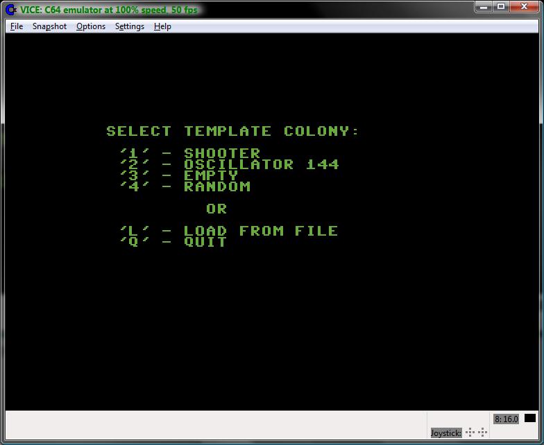 |
Game of Life - start
menu.
|
Depending on the user's choice, the
editor starts filled with the colony or empty. Editor encodes the
empty and life cells differently than the simulator. The empty cells
are represented by minus '-' signs, while the life cells are
represented with asterisks '*'. This approach has 2 advantages:
- User can recognize immediately in what mode the application is currently working (remember – there is no extra text information, the whole screen is taken by colony data presentation).
- The empty cells done with minus sign present a grid which makes it easier for user to design/modify the colony.
 |
Game of Life - editor
screen filled with random colony.
|
In editor, user can position the cursor
(visible as a reverse color rectangle) using cursor keys on the
keyboard and alter the cell status with space key. Other possible
functions are 'H' to display help screen, 'C' to clear all the cells
(requires confirmation), 'R' to fill cells with random values
(requires confirmation) and 'Q' to exit the editor and start
simulation. At the exit, user is prompted to save the colony to file,
which can be skipped.
 |
Game of Life - exit
editor, save to file prompt.
|
If user chooses to save the colony to
file, a prompt appears to enter the colony file name.
 |
Game of Life - save
colony, file name prompt.
|
The simple file name editor allows to
enter alpha-numeric string of up to 12 characters in length. User can
press DEL key to remove incorrectly entered characters. If the
entered file name is empty (RETURN key pressed with the cursor
positioned at the 1st character of the file name), the
Save operation is considered as canceled and program proceeds to
simulation. Otherwise, the program attempts to save the colony to
file. In case of I/O error, there is no action. Extension “.COL”
is added to the file name automatically.
Simulator starts in paused mode. User
can immediately see that program entered simulation mode because the
cells are now presented differently on the screen (Illustration
below).
 |
Game of Life – paused
simulator.
|
Pressing any key starts the simulation.
Please note the donut style cells (see Illustration below), which are
the cells marked to die in the next generation by the algorithm.
Newborn dots are not visible until the next generation is fully
created and the screen codes converted to the full dots or spaces
accordingly.
(NOTE: on the screen shot below, not
all the cells that are supposed to die in the next generation are yet
marked like donut, because the screen shot captured the screen in the
middle of the process)
 |
Game of Life - running
simulation.
|
At any moment during simulation user
can choose to quit application (requires confirmation), pause it, go
to editor and alter/save the colony, display the help screen or go
back to start menu (requires confirmation) using the keyboard
shortcuts presented on the help screen at the program start up.
 |
Game of Life - quitting
the application.
|
 |
Game of Life - the fun
is over.
|
Here is the link to source code. Look for a ZIP archive named ConwaysLife.
Thank you for visiting.
Marek Karcz
9/15/2013.
Sunday, February 3, 2013
IRQ sprite clock for Commodore-64.
Today I'd like to share with Commodore community this little piece I made back in the 1990-s - an IRQ sprite clock for Commodore-64.
Clock works in IRQ interrupt. Presentation is made with sprites (clock digits are mapped to sprite objects and displayed on screen). It is possible to use C-64 while this clock works. Oddly enough, this clock seems to be interfering with I/O while running on real hardware (unable to use disk drive or tape, will hung) but works fine in emulator. If you find the bug, please let me know!
; SPRITE IRQ CLOCK (C) Marek Karcz
; Code below compiles with CC65 assembler:
; cl65 --verbose --listing spriteclock.asm
; Use HEX editor to insert "00 C0" at the beginning
; of the executable to be able to run it on C64 or
; in emulator.
; Usage:
; LOAD"SPRITECLOCK",8,1
; CLR:NEW
; SYS49152,"HHMMSS"
; Where:
; HH - hours, MM - minutes, SS - seconds
; To turn the clock off:
; SYS49152
VIC = 53248 ;VIC Base
WSKSP0 = 2040 ;PTR. SPRITE 0
WSKSP1 = 2041 ;PTR. SPRITE 1
WSKSP2 = 2042 ;PTR. SPRITE 2
BLOK13 = 832 ;PTR. BEG. OF BLOCK 13
BLOK14 = 896 ;PTR. BEG. OF BLOCK 14
BLOK15 = 960 ;SEE ABOVE - BLOCK 15
IRQWKT = 788 ;IRQ VECT.
POBZNA = 121 ;READ CURR. BYTE
PRZECT = $AEFD ;CHECK COMMA
ANAWYR = 44446 ;PARSE EXPR.
POBTXT = 46978 ;GET STRING
.ORG $C000
JMP STEROW
LICZNIK: .BYTE 60 ;COUNTER
WZORCE: .BYTE 2,3,5,9,5,9 ;TEMPLATES
CZAS: .BYTE 1,2,0,0,0,0 ;TIME
LICZPOZ: .BYTE 1 ;POS. COUNTER
CYF0: .BYTE 0,252,204,204 ;DIGIT 0
.BYTE 204,204,204,252
CYF1: .BYTE 0,12,12,12 ;DIGIT 1
.BYTE 12,12,12,12
CYF2: .BYTE 0,252,12,12 ;DIGIT 2, etc...
.BYTE 252,192,192,252
CYF3: .BYTE 0,252,12,12
.BYTE 60,12,12,252
CYF4: .BYTE 0,204,204,204
.BYTE 252,12,12,12
CYF5: .BYTE 0,252,192,252
.BYTE 12,12,12,252
CYF6: .BYTE 0,252,192,192
.BYTE 252,204,204,252
CYF7: .BYTE 0,252,12,24
.BYTE 48,96,192,192
CYF8: .BYTE 0,252,204,204
.BYTE 252,204,204,252
CYF9: .BYTE 0,252,204,204
.BYTE 252,12,12,252
DWUKR: .BYTE 0,0,48,48 ;COLON
.BYTE 0,48,48,0
COPY: LDX #$00
LDY #$00
LOOP1: LDA CYF0,X
BLKNR: STA BLOK13,Y
CPX #7
BEQ POZ
INY
INY
INY
INX
JMP LOOP1
POZ: RTS
IRQROM: JMP $EA31
MAIN: DEC LICZNIK
BNE IRQROM
LDA #60
STA LICZNIK
LDA CZAS
LDX #3
CMP #2
BEQ NOC
LDX #9
NOC: STX WZORCE+1
LDX #5
NXTCYF: LDA CZAS,X
INC CZAS,X
CMP WZORCE,X
BNE KOP1
LDA #$00
STA CZAS,X
DEX
BPL NXTCYF
KOP1: LDA #$00
STA LICZPOZ
LDX #<CZAS
LDY #>CZAS
STX KOPIUJ+1
STY KOPIUJ+3
LDX #<BLOK13
LDY #>BLOK13
STX POS0B+1
STY POS0C+1
KOPIUJ: LDX #<CZAS
LDY #>CZAS
STX POS0+1
STY POS0+2
POS0: LDA CZAS
CMP #$00
BNE NIE00
LDX #<CYF0
LDY #>CYF0
POS0A: STX LOOP1+1
STY LOOP1+2
POS0B: LDX #<BLOK13
POS0C: LDY #>BLOK13
STX BLKNR+1
STY BLKNR+2
JSR COPY
JMP POS1
NIE00: CMP #$01
BNE NIE01
LDX #<CYF1
LDY #>CYF1
JMP POS0A
NIE01: CMP #$02
BNE NIE02
LDX #<CYF2
LDY #>CYF2
JMP POS0A
NIE02: CMP #$03
BNE NIE03
LDX #<CYF3
LDY #>CYF3
JMP POS0A
NIE03: CMP #$04
BNE NIE04
LDX #<CYF4
LDY #>CYF4
JMP POS0A
NIE04: CMP #$05
BNE NIE05
LDX #<CYF5
LDY #>CYF5
JMP POS0A
NIE05: CMP #$06
BNE NIE06
LDX #<CYF6
LDY #>CYF6
JMP POS0A
NIE06: CMP #$07
BNE NIE07
LDX #<CYF7
LDY #>CYF7
JMP POS0A
NIE07: CMP #$08
BNE NIE08
LDX #<CYF8
LDY #>CYF8
JMP POS0A
NIE08: LDX #<CYF9
LDY #>CYF9
JMP POS0A
POS1: INC KOPIUJ+1
LDA KOPIUJ+1
CMP #$00
BNE POS1A
INC KOPIUJ+3
POS1A: INC LICZPOZ
LDA LICZPOZ
CMP #1
BNE POS1B
LDX #<(BLOK13+1)
LDY #>(BLOK13+1)
POS1A1: STX POS0B+1
STY POS0C+1
JMP KOPIUJ
POS1B: CMP #2
BNE POS1C
LDX #<BLOK14
LDY #>BLOK14
JMP POS1A1
POS1C: CMP #3
BNE POS1D
LDX #<(BLOK14+1)
LDY #>(BLOK14+1)
JMP POS1A1
POS1D: CMP #4
BNE POS1E
LDX #<BLOK15
LDY #>BLOK15
JMP POS1A1
POS1E: CMP #5
BNE POS1F
LDX #<(BLOK15+1)
LDY #>(BLOK15+1)
JMP POS1A1
POS1F: JMP $EA31
START: LDX #$00
LDA #$00
STLOOP: STA BLOK13,X
STA BLOK14,X
STA BLOK15,X
INX
CPX #63
BEQ ST1
JMP STLOOP
ST1: LDX #$00
LDY #$00
ST1LOOP: LDA DWUKR,X
STA BLOK13+2,Y
STA BLOK14+2,Y
INX
CPX #8
BEQ ST2
INY
INY
INY
JMP ST1LOOP
ST2: LDX #13
STX WSKSP0
INX
STX WSKSP1
INX
STX WSKSP2
KOLOR: LDA #13
STA VIC+39
STA VIC+40
STA VIC+41
LDA #000110
STA VIC+16
LDA #215
LDX #50
STA VIC
STX VIC+1
LDA #7
STA VIC+2
STX VIC+3
ADC #48
STA VIC+4
STX VIC+5
LDA #000111
STA VIC+23
STA VIC+29
STA VIC+27
STA VIC+21
LDX #<MAIN
LDY #>MAIN
SEI
STX IRQWKT
STY IRQWKT+1
CLI
RTS
STEROW: JSR POBZNA
BEQ WYLACZ
JSR PRZECT
JSR ANAWYR
ROL 13
BCS NASTAW
ILLQUA: JMP 47000
NASTAW: JSR POBTXT
CMP #6
BNE ILLQUA
LDY #5
SEI
NASTPE: LDA (34),Y
SEC
SBC #48
STA CZAS,Y
DEY
BPL NASTPE
LDA #60
STA LICZNIK
CLI
JMP START
WYLACZ: LDX #$31
LDY #$EA
SEI
STX IRQWKT
STY IRQWKT+1
CLI
LDA #$00
STA VIC+21
RTS
In the next episode I will present a BASIC program that uses above clock to sound an alarm (sound and visual effects) at predefined time.
Thanks for reading.
Marek Karcz
2/3/2013
Clock works in IRQ interrupt. Presentation is made with sprites (clock digits are mapped to sprite objects and displayed on screen). It is possible to use C-64 while this clock works. Oddly enough, this clock seems to be interfering with I/O while running on real hardware (unable to use disk drive or tape, will hung) but works fine in emulator. If you find the bug, please let me know!
; SPRITE IRQ CLOCK (C) Marek Karcz
; Code below compiles with CC65 assembler:
; cl65 --verbose --listing spriteclock.asm
; Use HEX editor to insert "00 C0" at the beginning
; of the executable to be able to run it on C64 or
; in emulator.
; Usage:
; LOAD"SPRITECLOCK",8,1
; CLR:NEW
; SYS49152,"HHMMSS"
; Where:
; HH - hours, MM - minutes, SS - seconds
; To turn the clock off:
; SYS49152
VIC = 53248 ;VIC Base
WSKSP0 = 2040 ;PTR. SPRITE 0
WSKSP1 = 2041 ;PTR. SPRITE 1
WSKSP2 = 2042 ;PTR. SPRITE 2
BLOK13 = 832 ;PTR. BEG. OF BLOCK 13
BLOK14 = 896 ;PTR. BEG. OF BLOCK 14
BLOK15 = 960 ;SEE ABOVE - BLOCK 15
IRQWKT = 788 ;IRQ VECT.
POBZNA = 121 ;READ CURR. BYTE
PRZECT = $AEFD ;CHECK COMMA
ANAWYR = 44446 ;PARSE EXPR.
POBTXT = 46978 ;GET STRING
.ORG $C000
JMP STEROW
LICZNIK: .BYTE 60 ;COUNTER
WZORCE: .BYTE 2,3,5,9,5,9 ;TEMPLATES
CZAS: .BYTE 1,2,0,0,0,0 ;TIME
LICZPOZ: .BYTE 1 ;POS. COUNTER
CYF0: .BYTE 0,252,204,204 ;DIGIT 0
.BYTE 204,204,204,252
CYF1: .BYTE 0,12,12,12 ;DIGIT 1
.BYTE 12,12,12,12
CYF2: .BYTE 0,252,12,12 ;DIGIT 2, etc...
.BYTE 252,192,192,252
CYF3: .BYTE 0,252,12,12
.BYTE 60,12,12,252
CYF4: .BYTE 0,204,204,204
.BYTE 252,12,12,12
CYF5: .BYTE 0,252,192,252
.BYTE 12,12,12,252
CYF6: .BYTE 0,252,192,192
.BYTE 252,204,204,252
CYF7: .BYTE 0,252,12,24
.BYTE 48,96,192,192
CYF8: .BYTE 0,252,204,204
.BYTE 252,204,204,252
CYF9: .BYTE 0,252,204,204
.BYTE 252,12,12,252
DWUKR: .BYTE 0,0,48,48 ;COLON
.BYTE 0,48,48,0
COPY: LDX #$00
LDY #$00
LOOP1: LDA CYF0,X
BLKNR: STA BLOK13,Y
CPX #7
BEQ POZ
INY
INY
INY
INX
JMP LOOP1
POZ: RTS
IRQROM: JMP $EA31
MAIN: DEC LICZNIK
BNE IRQROM
LDA #60
STA LICZNIK
LDA CZAS
LDX #3
CMP #2
BEQ NOC
LDX #9
NOC: STX WZORCE+1
LDX #5
NXTCYF: LDA CZAS,X
INC CZAS,X
CMP WZORCE,X
BNE KOP1
LDA #$00
STA CZAS,X
DEX
BPL NXTCYF
KOP1: LDA #$00
STA LICZPOZ
LDX #<CZAS
LDY #>CZAS
STX KOPIUJ+1
STY KOPIUJ+3
LDX #<BLOK13
LDY #>BLOK13
STX POS0B+1
STY POS0C+1
KOPIUJ: LDX #<CZAS
LDY #>CZAS
STX POS0+1
STY POS0+2
POS0: LDA CZAS
CMP #$00
BNE NIE00
LDX #<CYF0
LDY #>CYF0
POS0A: STX LOOP1+1
STY LOOP1+2
POS0B: LDX #<BLOK13
POS0C: LDY #>BLOK13
STX BLKNR+1
STY BLKNR+2
JSR COPY
JMP POS1
NIE00: CMP #$01
BNE NIE01
LDX #<CYF1
LDY #>CYF1
JMP POS0A
NIE01: CMP #$02
BNE NIE02
LDX #<CYF2
LDY #>CYF2
JMP POS0A
NIE02: CMP #$03
BNE NIE03
LDX #<CYF3
LDY #>CYF3
JMP POS0A
NIE03: CMP #$04
BNE NIE04
LDX #<CYF4
LDY #>CYF4
JMP POS0A
NIE04: CMP #$05
BNE NIE05
LDX #<CYF5
LDY #>CYF5
JMP POS0A
NIE05: CMP #$06
BNE NIE06
LDX #<CYF6
LDY #>CYF6
JMP POS0A
NIE06: CMP #$07
BNE NIE07
LDX #<CYF7
LDY #>CYF7
JMP POS0A
NIE07: CMP #$08
BNE NIE08
LDX #<CYF8
LDY #>CYF8
JMP POS0A
NIE08: LDX #<CYF9
LDY #>CYF9
JMP POS0A
POS1: INC KOPIUJ+1
LDA KOPIUJ+1
CMP #$00
BNE POS1A
INC KOPIUJ+3
POS1A: INC LICZPOZ
LDA LICZPOZ
CMP #1
BNE POS1B
LDX #<(BLOK13+1)
LDY #>(BLOK13+1)
POS1A1: STX POS0B+1
STY POS0C+1
JMP KOPIUJ
POS1B: CMP #2
BNE POS1C
LDX #<BLOK14
LDY #>BLOK14
JMP POS1A1
POS1C: CMP #3
BNE POS1D
LDX #<(BLOK14+1)
LDY #>(BLOK14+1)
JMP POS1A1
POS1D: CMP #4
BNE POS1E
LDX #<BLOK15
LDY #>BLOK15
JMP POS1A1
POS1E: CMP #5
BNE POS1F
LDX #<(BLOK15+1)
LDY #>(BLOK15+1)
JMP POS1A1
POS1F: JMP $EA31
START: LDX #$00
LDA #$00
STLOOP: STA BLOK13,X
STA BLOK14,X
STA BLOK15,X
INX
CPX #63
BEQ ST1
JMP STLOOP
ST1: LDX #$00
LDY #$00
ST1LOOP: LDA DWUKR,X
STA BLOK13+2,Y
STA BLOK14+2,Y
INX
CPX #8
BEQ ST2
INY
INY
INY
JMP ST1LOOP
ST2: LDX #13
STX WSKSP0
INX
STX WSKSP1
INX
STX WSKSP2
KOLOR: LDA #13
STA VIC+39
STA VIC+40
STA VIC+41
LDA #000110
STA VIC+16
LDA #215
LDX #50
STA VIC
STX VIC+1
LDA #7
STA VIC+2
STX VIC+3
ADC #48
STA VIC+4
STX VIC+5
LDA #000111
STA VIC+23
STA VIC+29
STA VIC+27
STA VIC+21
LDX #<MAIN
LDY #>MAIN
SEI
STX IRQWKT
STY IRQWKT+1
CLI
RTS
STEROW: JSR POBZNA
BEQ WYLACZ
JSR PRZECT
JSR ANAWYR
ROL 13
BCS NASTAW
ILLQUA: JMP 47000
NASTAW: JSR POBTXT
CMP #6
BNE ILLQUA
LDY #5
SEI
NASTPE: LDA (34),Y
SEC
SBC #48
STA CZAS,Y
DEY
BPL NASTPE
LDA #60
STA LICZNIK
CLI
JMP START
WYLACZ: LDX #$31
LDY #$EA
SEI
STX IRQWKT
STY IRQWKT+1
CLI
LDA #$00
STA VIC+21
RTS
In the next episode I will present a BASIC program that uses above clock to sound an alarm (sound and visual effects) at predefined time.
Thanks for reading.
Marek Karcz
2/3/2013
Subscribe to:
Posts (Atom)